Why Choose a Valve Actuator for Industrial Systems?
Industrial systems rarely fail in dramatic ways. More often, a valve responds slowly, sticks, or stops halfway. These small delays can disturb pressure, temperature, flow, and production quality. A reliable Valve Actuator turns control signals into consistent mechanical movement. It opens, closes, or positions a valve with measured force.
Dr. Béla G. Lipták, a respected process-control authority, wrote, “The control valve is the most common final control element.” His observation explains the actuator’s importance. The valve may be the visible component, but the actuator supplies its working motion. In a chemical plant, for example, a pneumatic actuator can move a heavy valve within seconds. In a water-treatment line, an electric actuator can adjust flow repeatedly without manual intervention.
Control matters.
Choosing an actuator requires more than checking torque. Engineers must examine valve type, operating pressure, temperature, cycle frequency, available power, and environmental conditions. A dusty outdoor installation may need stronger enclosure protection. A high-cycle process may need accurate feedback and dependable internal parts. Fail-safe behavior also deserves careful attention. Should the valve close, open, or remain fixed after power loss?
No actuator is perfect. Oversizing can cause poor control and unnecessary expense. Undersizing can leave the valve unable to move. I have seen specifications look correct on paper, yet perform poorly after installation. That gap deserves honest review. This article explores why industrial systems choose Valve Actuator technology, how different designs perform, and which practical details influence long-term reliability.
Why Choose a Valve Actuator for Industrial Systems?
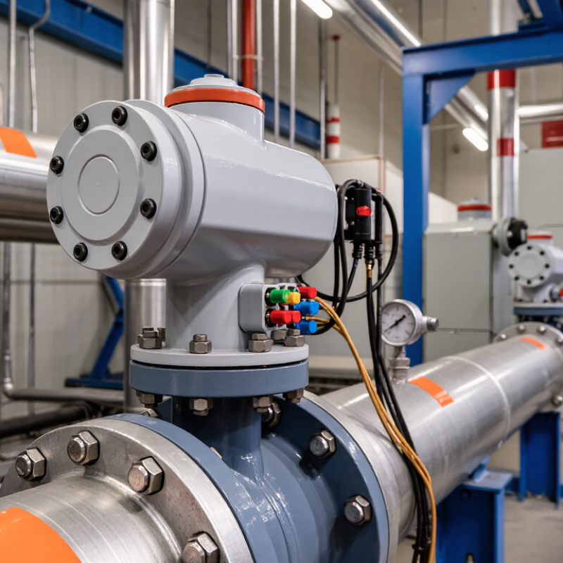
A valve actuator converts an electrical, pneumatic, or hydraulic signal into controlled valve movement. It moves the valve. This device enables automated flow control without constant manual adjustment. Electric actuators suit accurate positioning and distributed control. Pneumatic actuators often provide rapid movement and useful fail-safe action. Hydraulic units deliver high torque for demanding applications.
In practice, selection begins with valve torque, pressure, temperature, cycle frequency, and required response time. Feedback from position sensors helps a control system detect incomplete travel. Limit switches can prevent over-rotation. For hazardous or safety-related processes, engineers should review IEC 61508 and IEC 61511 requirements. An actuator is not merely a motor attached to a valve. Its enclosure, mounting interface, control signal, and emergency behavior all affect system reliability.
The International Energy Agency reported that industry used about 37% of global final energy in 2022, according to its Energy Efficiency 2023 report. Efficient flow regulation can reduce unnecessary pumping, throttling, and compressed-air demand, although savings depend on the whole process. A poorly sized actuator may hunt, stall, or wear the valve seat. That lesson is easy to forget. During commissioning, technicians should compare commanded position with actual travel under real load. A spreadsheet can miss pipe friction, cold-start conditions, or rapid pressure changes. Small details matter. The best choice is rarely perfect, but it should be traceable to operating data, recognized standards, and observed field behavior.
| Data Dimension | Industrial Valve Actuator Information | Operational Relevance |
|---|---|---|
| Definition | A valve actuator is a mechanical device that moves a valve to open, close, or regulate fluid flow in response to a control signal or local command. | It converts electrical, pneumatic, or hydraulic energy into controlled valve movement. |
| Primary Role | Automates the positioning of process valves in piping, equipment, and fluid-handling systems. | Reduces the need for manual operation and enables repeatable flow control. |
| Main Actuator Types | Electric, pneumatic, and hydraulic actuators. | Selection depends on available utilities, required torque or thrust, operating environment, response time, and safety requirements. |
| Electric Actuators | Use an electric motor and mechanical transmission to rotate or linearly move a valve. | Suitable where electrical power and precise position control are available; commonly used for on/off and modulating service. |
| Pneumatic Actuators | Use compressed air to operate a diaphragm, piston, or vane mechanism. | Provide fast response and are widely used where compressed air is available or electrical ignition sources must be minimized. |
| Hydraulic Actuators | Use pressurized hydraulic fluid to generate rotary or linear force. | Appropriate for applications requiring high force or torque, including large valves and demanding process conditions. |
| Valve Motion | Rotary actuators turn the valve shaft; linear actuators move the valve stem in a straight line. | Rotary motion is typical for ball, butterfly, and plug valves, while linear motion is common for globe and gate valves. |
| Control Modes | On/off, open-close positioning, and modulating control. | Modulating actuators can position a valve at intermediate openings to help maintain flow, pressure, level, or temperature. |
| Control Signals | Common signals include discrete electrical commands, analog signals such as 4–20 mA, and digital industrial communication. | Signal compatibility allows integration with programmable controllers, distributed control systems, and supervisory control systems. |
| Fail-Safe Action | Fail-open, fail-closed, or fail-in-place behavior can be designed according to the process risk. | The selected position can help limit hazards during loss of power, control signal, or instrument air. |
| Position Feedback | Limit switches, potentiometers, encoders, or electronic position transmitters may report valve position. | Feedback supports monitoring, alarms, sequence control, and verification that the commanded position was achieved. |
| Torque or Thrust Requirement | The actuator must provide sufficient torque for rotary valves or thrust for linear valves under the most demanding operating condition. | Correct sizing helps prevent incomplete travel, excessive wear, seat damage, and unreliable shutoff. |
| Response Speed | Actuator speed varies with actuator design, valve size, load, supply pressure or voltage, and control settings. | Fast movement can support emergency isolation, while controlled movement can reduce water hammer and process disturbances. |
| Automation Benefits | Remote operation, repeatable positioning, automatic sequencing, and centralized monitoring. | Improves process consistency and allows operators to control valves from safer or more accessible locations. |
| Safety Contribution | Actuators can support emergency shutdown, isolation, interlocking, and predefined safe-position functions. | Automated valve movement can reduce personnel exposure to high temperature, pressure, toxic media, or hazardous areas. |
| Typical Industries | Water and wastewater, power generation, chemical processing, oil and gas, food processing, pharmaceuticals, mining, and HVAC. | The actuator type and enclosure are selected according to the process medium, pressure, temperature, hygiene, and area classification. |
| Environmental Considerations | Important factors include ambient temperature, moisture, dust, corrosion, vibration, and potentially explosive atmospheres. | Proper enclosure protection and area-appropriate construction improve reliability and service life. |
| Maintenance Factors | Inspection may include linkage alignment, lubrication where applicable, seals, electrical connections, air supply quality, and position calibration. | Routine maintenance helps detect loss of performance before it causes process interruption or unsafe valve behavior. |
| Key Selection Criteria | Valve type, required torque or thrust, stroke or rotation angle, duty cycle, fail action, control signal, supply energy, environment, and safety requirements. | A properly matched actuator provides dependable flow control without unnecessary energy use or mechanical stress. |